Showing posts with label Revit how to. Show all posts

Back to Basics – Conceptual Masses in Revit 2011

image

I am still surprised by the amount of questions and queries I get from users who are trying / starting to use Revit’s conceptual massing tools in either RAC 2010 or RAC 2011. The most common queries relate to how you actually create a particular form. I am suppose pre 2010 it was straight forward as we had extrude, revolve, sweep, blend and swept blend. The way you used these form making tools was very explicit; need to create an extruded form? Then use the extrude tool. Revit 2010 changed all that with a far more flexible approach to form making, but to some extent it tossed away the rule book and I believe that is what has confused some users. If you don’t do a lot of massing in Revit, this new paradigm can also lead to confusion and a certain amount of head banging!! I’ve had experienced Revit users get totally stumped when creating even the most basic forms. Once you understand the behaviour and the philosophy to form making, creating complex forms gets a lot easier.

So it made sense to create a series of short videos which explained how to create some common forms in Revits conceptual design environment. Experienced users who use the tools will know all this, but for those that don’t, I hope this is of assistance. I have deliberately avoided any voice over, so you force yourself to review the tools and commands being picked. It is all about creating the forms and I deliberately does not delved into model lines versus reference lines, pure geometry only. I am sure there are many ways to create some of these forms, but these in my view these are the most obvious steps.

You will find videos which you how to…..

  • Extrude
  • Revolve
  • Blend
  • Sweep
  • Swept Blend
  • Cone
  • Dome
  • Sphere
  • Torus
  • Loft 1
  • Loft 2
  • Pyramid


1. Extrude


2. Revolve


3. Blend


4. Sweep


5. Swept Blend


6. Cone


7. Dome


8. Sphere


9. Torus


10. Loft 1


11. Loft 2


12. Pyramid

Adapt your points of view – Revit 2011

A few years back when I worked for a well known UK reseller, a colleague and I put together a presentation to demonstrate how Inventor and Revit could work together. Part of this presentation showed how to model in Inventor and then pass the geometry to Revit as a SAT file for use within a Revit project. Of particular interest at the time was Inventors adaptive capabilities and we used these to great affect in a structural atrium support solution.

image

Whilst this was a virtual design concept, the original idea came about from a real project I had been involved in 12 years earlier with Househam Henderson Architects. This was for a TV company that were refurbishing a building, turning it into their new offices and studios in central London. The building being renovated had an enclosed court yard which was opened to the elements, but the plan was to enclose this courtyard with a glazed roof to form an atrium. This would provide a cafe and a social area for staff and visiting guests. One issue was that the new glazed roof would need supporting from the atrium floor level. 

1276_N11

So a structural tree support system was designed to support the roof. At the time this was modelled in AutoCAD release 13, yes you did read that right, that's how old the project is! The big challenge at the time was the scheme constantly changed as the designer and the structural engineer refined the concept further. Load distribution was a nightmare! My special thanks goes out to Househam Henderson for allowing me to use the image above.

So when I saw the new adaptive component family in Revit 2011, I immediately got excited as I remembered the modelling challenges I had encountered in the past. Whilst Inventors adaptive tools resolve the problem, I wanted to do this in Revit! :-)

image 

Understanding how the new adaptive points react and their various parameters is without doubt the key. This short video introduces you to the new adaptive family and demonstrates how to create a simple structural tree support. Hope this is useful…..

Pointless stuff, Offset parameter in Revit massing

This article builds on recent posts on the use of Reference point, when working in the conceptual massing environment. The more I use them, the more I realise how powerful they are.

If you place a “Reference Point” and take a look at its Instance properties, you will discover its a System Family.

image

You can control how it displays in the conceptual environment; for instance you can change the Show Reference Planes Parameter. You are provided with three options “Never”, “When Selected”,  “Always”. You can also control its visibility by enabling or disabling the “Visible” parameter.

image

Under the Graphics section we can say whether its “Driven by Host” and you will also see an “Offset” parameter. We can also name the point. Lets focus on the “Offset” parameter.

We can drive the offset parameter, thus moving the point by adding a figure into the “Value”. This offset distance is based on the plane the point was originally position on. So if we add 1m into the offset it will move the point 1m in a “Z” direction, assuming it was position on the X,Y plane.

image

Now the smart thing here is because the point has a total of three planes, XY, ZY,ZX, we can also place points on these planes and drive points using there offset from the planes.

image

Take a look at the video which should hopefully explain this in more detail.

Helix from lines and points

Following two great blog posts on creating helix’s; one from Buildz blog and the other from BIM troublemaker, I thought I’d run through my solution to this problem. I have been experimenting with this for a few weeks now; not being great at math, I wanted to see if I could create a helix without the need for heavy formula.

image

Hopefully these two videos will explain my approach; I’ve had to split the the how-to video into two parts, due the 11 minute YouTube limits! They include all the normal mistakes, so don’t expect a super slick video. :-)

If you interested, you can also download the family from here.

Get the hosted point?

This post comes from experimenting with hosted points on lines and arcs and attempting to create a helical form in the massing environment similar to Zach Kron’s recent post. I guessed that you could do something similar using lines connected to hosted points on circles.

So let go back to basics. Points can be hosted to lines, arcs, splines, circles and ellipses (either reference line or lines). Just draw a line or reference line then choose the point tool and place the point on the line. It will snap to the line and  you will  notice it will change in size and will now include a work plane.

image

If you select the point and choose properties, you will discover that there is now a hosted parameter. This parameter drives the position of the point and it goes from 0 to 1. “0” being one end and “1” the other end. If you wanted to place the point half way along the line, plug in 0.5, voila the point is position half way along the line.

image

So lines are straight forward, what about circles or even ellipses? Hmmmmm Ok, go ahead do the same thing, but this time draw a circle as a line or reference line and place a point on the circle. Go check the properties of the Hosted Parameter…. No 0 to 1???? some other weird combination of figures????!!!

image

So what’s going on here? Well I’m no mathematician, so after a bit of investigation I discovered that points are managed differently on closed elements such as circles. You need to go back to do some math…

So the hosted parameter value for a circle is 2pi

(where pi is 3.1415926535897932384626433832795)

therefore  2 x 3.141593 is equal to 6.283186 radians

So the hosted point can have a value between 0 to 6.28318 depending on where it is on the circle.

So to split the circle into degrees

1 degree=2pi/360=0.017453 radians

With this logic in mind try this, create a circle in the massing environment and host a point on the circle. Go the the hosted parameters, then plug in the following figures and watch the position of the points change.

  1. 0 degrees - 0 x 0.017453 = 0
  2. 90 degrees – 90 x 0.017453 = 1.570796
  3. 180 degrees – 180 x 0.017453 = 3.141593
  4. 270 degrees – 270 x 0.017453 = 4.712389
  5. 360 degrees – 360 x 0.017453 = 6.28308

This opens up to interesting opportunities and allowed me to create the helix using points and lines along with nested families. I’ll show you how I did this in another post……

image

My Pumpkin wins a prize!

image

My thanks goes to Zach Kron at Buildz blog for running the inaugural pumpkin modelling competition! My modelling effort managed me a first in the “good” category and my collegue William  managed a first in the “mostest parametric” category, with his stunning Grasshopper Rhino pumpkin, a big UP for the HOK boys!

It was certainly a good laugh, but for me its actually a great learning exercise, because you can push the tools of your trade in a direction which you wouldn’t normally get a chance to do. This will reap benefits when you come to have to create something on a real project, not that you will see many pumpkins in my projects! :-)

image

I had to jump through a few hoops to get to the end solution, but I applied a bit of Revit purist approach to solving the problem, which you can view in this video. Enjoy and I hope it inspires.

William’s Parametric Bridge Recipe!

As promised, my colleague William Lopez Campo emailed me the Parametric Bridge Recipe he used for his winning design as last weeks Berlin Design Slam!

bridge_recipe

Ingredients consisted of :-

  • Context Mesh X1
  • Parametric Void X1
  • Parametric Controlling Box X1
  • Variable Parameters X4
  • A-Level Formulas X3
  • Place Holder Family X2
  • Basic Solids X3

Method :-

  1. Open Context Mesh, add slab and slab edge to form the base of the bridge.
  2. In a bowl mix parametric box, the controlling parameters and the variable with A-level formulas to get a formula driven box.
  3. Generate the solids from the edges of the box, so they follow the constraints of the ‘formulas’.
  4. Load the parametric assemble in the first place holder family, and this one in the bridge.
  5. Create various box types for the shape to follow alternative shapes and assign instances of the place holder family.
  6. Refine position and mirror along axis of the bridge.
  7. Replace placeholder with full instance version and simmer a few minutes.

IMAGE-04

Spikey Panels in Revit Architecture 2010

One of the cool new features in Revit Architecture 2010 is the new curtain wall pattern based family. If anybody has seen Zach Kron's Buildz blog you will have seen some of the cool stuff he does with this new family. Now a few years ago I remember playing with curtain wall panels (old school Revit) and trying to create a spikey hedgehog type form. The trouble back then was it was not possible to build a cw panel the would fit into a double curved surface.

spikey panels 2008

Fast forward to Revit 2010 and its finally possible!

spikey panels

Take a look at this video on how I created the panel above. I hope you find this useful.

How to create a sheared tube in Revit 2010

image

Here is an interesting challenge that somebody gave me last week. How can you create a extruded tube in 2010 and then  shear the tube so that the circles that make up the tube remain concentric top and bottom? After thinking about it, I came up with this as a solution. A combination of points and reference lines will solve the problem. Enjoy. :-)

Useful workflow? - 3dsmax to Sketchup to Revit

This query came up the other day....I've created a form in 3dmax Design 2009, how can I get this into Revit? Revit generally prefers solid geometry to be exported for use within its massing environment. So either DWG's containing solids or ascii SAT files. The problem is that 3dsmax can't export meshes as solids unless you purchase a 3rd party application. However, AutoCAD 2010 should come to the rescue as it will allow you to convert meshes to solids. So how else can we get 3dsmax geometry into Revit so that we can use the "by face" tools? In reality you should be able to go straight from 3dsmax as a DWG into Revit, but this sometimes isn't that successful. So how about Sketchup? I like Sketchup as an application, but I would never want to use it as a replacement to my beloved Revit. But it does seem to act well as a useful intermediate file conversation tool between 3dsMAX are Revit. So how do we go about doing this?

Start by Creating your geometry in 3dsmax, however you will need to convert this to a polymesh surface.

11_max

Next save the mesh out as a DWG file.

22_max

Then open the resulting DWG file in Google Sketchup, this can even be the free Google Sketchup as we don't need any features in Sketchup apart from being able to save as an SKP file. Open the DWG by going to file pulldown menu > import and choose DWG.

33_max

This will import the DWG into Sketchup, although make sure you have the correct unit set, you can do this by clicking the options button in the import dialogue box. If the model from Max was in millimetres, set the units in Sketchup to be millimetres.

55_max

Once you have imported the 3dsmax geometry into Sketchup you may need to do a few fixes to the geometry, but this is easily achieved by infilling any missing faces with the pencil tool.

44_max

Then save this file as a Sketchup file, file pulldown menu > saveas.

Now go back to Revit and start a new mass.

66_max

Then import your Sketchup model previously saved into the inplace mass. File pulldown menu > import/link > CAD formats.

77_max

In the import dialogue, choose Sketchup as the file type to import.

88_max

This will import the Sketchup geometry into the mass.

99_max

You can then go ahead and use the curtain system by face tools on the mesh to build the form.

222_max

333_max

This approach is reasonably successfully but it does depend on the complexity of the form create.

Comparing Revit models and drawings

This question comes up on a fairly regular basis, how can I compare two Revit drawings to see what has changed between revisions? Also, how can I compare two different versions of the Revit model to see what has changed?

In this post we will look at three different tools that can help facilitate this.I am sure their are other tools available to enable us to do this, but I have tried to highlight the most common ones which many of us have installed on our laptops or workstations.

Model Compare

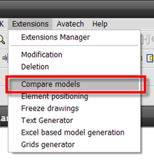
The Model Compare tool is part of the Extensions for Revit utilities which can be downloaded and installed from the Autodesk subscription site. Originally only available for Revit Structure users, Autodesk finally saw sense last year and released it for all of the disciplines. It's very easy to use; you start by opening the two models you want to compare, then choose model compare from the extensions pulldown menu.

mc_1

The application will the start and will look for differences between the two models. Once the comparison has been completed, you will be presented with a dialogue box which lists the two models and highlights general information relating to the two projects.

mc_2

You can then choose to review the difference in elements by selecting "elements" in the menu on the far left hand side of the dialogue box. mc_3

You can then use the "Comparison Type"  check boxes to change how the elements in the models are compared.

mc_4

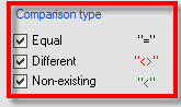
You have the ability to review elements as follows:-

mapped equally to one another "="
different to one another "<>"
no longer exist in the project  "<"

The report tool allows you to generate a report of the compared models. This can be saved as an MHT or html  file or you can export to Word or Excel as well as being able to print the report directly from the dialogue box.

mc_5

mc_6 mc_7

Below you will find a typical report exported to Excel.

mc_8

Drawing Compare - DWF

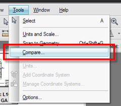
You  can also compare drawing output from Revit using Autodesk Design Review 2009. However, you  need to publish your drawings in DWF format from Revit, to start with. Then open one of the DWF's in Autodesk Design Review 2009 and choose compare from the tools pulldown menu.

mc_9

You will be presented with the following dialogue box.

mc_10

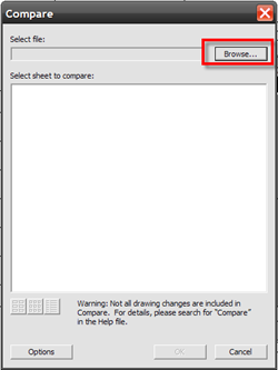
You can then choose the target DWF you want to compare, click the browse icon to locate the DWF, then choose "ok". Design Review will in essence compare the two different DWF outputs and highlighting what has changed by adding additional markup to the DWF.

mc_11

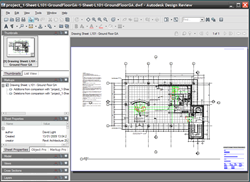
This additional markup can be saved in the DWF, but you also have the ability to load this back into Revit if required. This is achieved by choosing import/link in Revit then selecting the DWF you added to the markup to. The markup will then appear as a markup layer in Revit.

mc_12 

Drawing Compare - PDF

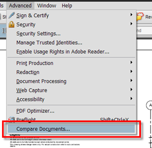
OK, DWF is fine, but what if you published all you drawings from Revit using PDF? In Acrobat Professional we can do something similar to the Compare functionality found in Design Review. Start Acrobat Pro and choose a suitable PDF created from Revit, then from the advanced pulldown menu choose "Compare Documents".

 mc_15

Again this will open a dialogue box which will allow you to browse to the PDF you want to compare against.

mc_13

There are different types of comparisons that you can use  and you also have the ability to create two different report types based on the comparisons found. 

A side by side report provides you with this output:-

mc_14

A consolidated Report provides you with this type of report, which just balloons the various changes:-

mc_145

There you have it, three different ways to compare differences between models and drawings. I guess that some of these may be obvious to the Revit user, nevertheless it fails to amaze me that many users and document reviewers are still not using digital tools to compare differences and changes, instead opting for the old school approach of printing the drawing out to paper and using a magic marker to highlight changes!