

Shaan Hurley has posted a short (about 4 minutes) video demonstrating Dimensional and Geometric Parametric Constraints available in AutoCAD 2010. Here it is:
Thanks for sharing with us Shaan.
Drivers Download
Showing posts with label AutoCAD 2010. Show all posts
Showing posts with label AutoCAD 2010. Show all posts
Shaan Hurley has posted a short (about 4 minutes) video demonstrating Dimensional and Geometric Parametric Constraints available in AutoCAD 2010. Here it is:
Thanks for sharing with us Shaan.
Thanks for sharing with us Shaan.
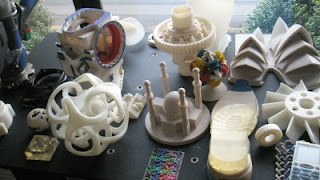
While I was at Autodesk’s office in San Francisco, I was fortunate enough to have been given a tour of many of Autodesk’s Labs projects. John Schmier, Autodesk Labs Engineer and Evangelist, was very happy to show off several of the Labs Projects. In this tour there were many examples of 3D printing. The ability to send a file to a 3D printer right out of AutoCAD was added to AutoCAD 2010. It processes and sends your model to a 3D printing service. You will receive your model in the mail after a few days time! With the cost of 3D printers around $30,000 apiece (that price various greatly depending on what it does, etc.), it can very difficult for firms to have this ability in house.
Here are some photos of what Autodesk had on display.
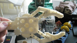
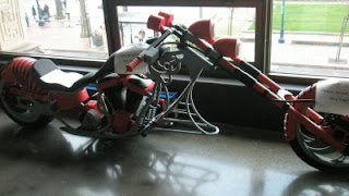

If you went to Autodesk University 2008 you will probably recognize the motorcycle in the photos. Every part was created via 3D printing technology.
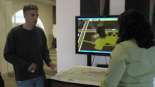
 Many of you might recognize the Touch Screen from AU. It is a giant screen that has touch interface. Depending on which program you are running, you can use a certain amount of touch points to manipulate your files. This display had touch enabled version of Autodesk Design Review and Autodesk Mudbox. Using different combinations of touch points and movement you can navigate through a DWG file or you could render a 3D object in Mudbox. Autodesk is studying ways humans can interface with computers. The software is there, but making it so it can run on different hardware is evidently the issue.
Windows 7 is supposed to support touch technology, so we should be seeing more and more hardware and software available with touch interface technology. HP also has hardware out that can handle up to four touch points, but Autodesk’s software has been developed to work with eight to ten. The software and the hardware are still in need of coming together before this technology type becomes more mainstream.
One of the other pieces of technology highlighted in my tour featured other ways of interfacing with the computer. Autodesk is looking for more ways to take everyday hardware that is relatively inexpensive and apply it to new ways for humans to interface with computers. In this example, Autodesk took a remote control from a Nintendo Wii (download the driver here) and was navigating through a Design Review file. Another device was nothing more than a cardboard cube. A basic web cam was looking at the device and could recognize which side was up! It was using a form of Augmented Reality. To turn the drawing object on the computer screen so that the back was displayed, rotate the cube in your hand until the back was showing. It works just like the View Cube in AutoCAD and Design Review, but it is a physical object that a person can hold in his or her hands. It can make presenting a drawing more simple for those that are not as familiar with the display controls inside Autodesk products.
 Using a simple web cam, the Labs had a display that can easily be applied to spatial planning. This was also using Augmented Reality (click the link to see a YouTube video of this tech being demonstrated.) There was a computer, large screen and a web cam that was viewing a flat display on a table in front of the screen. The display was flat and had tiles on it. Each tile had a picture of a building, parking layout, or other equipment or buildings. The tiles on the display mat were read by the web cam and recognized to represent 3D models on the screen. The software running could then analyze the data shown and conduct process like light studies or airflow around the buildings. This tool is meant to aid spatial planners of all sorts to be able to look at objects and see how they interact with each other. City Planners and warehouse designers could quickly throw down some tiles and see where they can fit, how they affect the surrounding area, and more.
The last bit of technology shown that I want to talk about was the Boom Chameleon. The Labs department has been displaying this bit of tech for some time now and I was glad to get a chance to see it in person. There are many different applications that can take advantage of this device. The Boom Chameleon demonstrates how car manufacturers can save millions of dollars working on prototypes for new car designs. The Boom on display takes a 3D model of a car (in this case, but it could be anything) and allows the user to walk around it, inspecting it in real time and size. The device consists of a platform with a tower and boom. There is a screen at the end of the boom that can be lifted, lowered, and spun to simulate a person looking at a real car. Where you move the boom and screen will determine where you are looking. It replicates a physical car. Evidently it take about a million dollars for a car company to create a full scale model of a new car. With the technology of the Boom Chameleon, they no longer have to create as many real models. They can conduct inspections of the new design and get a good feel of how the car will look before it exists. It is estimated that this technology could reduce the amount of models created by 50%.
This technology can also be applied to building inspections and constructions. Using the Chameleon and BIM, users can take the boom out to an existing building, move it around a room and "see" what is inside the walls, floor and ceiling before they start punching holes and destroying whats inside. Very useful, as long as the data is correct!
There was a lot of exciting technology on display by Autodesk Labs at the San Francisco office and I greatly appreciated John’s tour. If you haven't, visit Autodesk Labs and Scott Sheppard's Blog. You may be surprised by what they have available. Oh, and here is a link from Scott's blog about the event I attended.
Happy CADDING.
Here are some photos of what Autodesk had on display.


If you went to Autodesk University 2008 you will probably recognize the motorcycle in the photos. Every part was created via 3D printing technology.
 Many of you might recognize the Touch Screen from AU. It is a giant screen that has touch interface. Depending on which program you are running, you can use a certain amount of touch points to manipulate your files. This display had touch enabled version of Autodesk Design Review and Autodesk Mudbox. Using different combinations of touch points and movement you can navigate through a DWG file or you could render a 3D object in Mudbox. Autodesk is studying ways humans can interface with computers. The software is there, but making it so it can run on different hardware is evidently the issue.
Windows 7 is supposed to support touch technology, so we should be seeing more and more hardware and software available with touch interface technology. HP also has hardware out that can handle up to four touch points, but Autodesk’s software has been developed to work with eight to ten. The software and the hardware are still in need of coming together before this technology type becomes more mainstream.
One of the other pieces of technology highlighted in my tour featured other ways of interfacing with the computer. Autodesk is looking for more ways to take everyday hardware that is relatively inexpensive and apply it to new ways for humans to interface with computers. In this example, Autodesk took a remote control from a Nintendo Wii (download the driver here) and was navigating through a Design Review file. Another device was nothing more than a cardboard cube. A basic web cam was looking at the device and could recognize which side was up! It was using a form of Augmented Reality. To turn the drawing object on the computer screen so that the back was displayed, rotate the cube in your hand until the back was showing. It works just like the View Cube in AutoCAD and Design Review, but it is a physical object that a person can hold in his or her hands. It can make presenting a drawing more simple for those that are not as familiar with the display controls inside Autodesk products.
 Using a simple web cam, the Labs had a display that can easily be applied to spatial planning. This was also using Augmented Reality (click the link to see a YouTube video of this tech being demonstrated.) There was a computer, large screen and a web cam that was viewing a flat display on a table in front of the screen. The display was flat and had tiles on it. Each tile had a picture of a building, parking layout, or other equipment or buildings. The tiles on the display mat were read by the web cam and recognized to represent 3D models on the screen. The software running could then analyze the data shown and conduct process like light studies or airflow around the buildings. This tool is meant to aid spatial planners of all sorts to be able to look at objects and see how they interact with each other. City Planners and warehouse designers could quickly throw down some tiles and see where they can fit, how they affect the surrounding area, and more.
The last bit of technology shown that I want to talk about was the Boom Chameleon. The Labs department has been displaying this bit of tech for some time now and I was glad to get a chance to see it in person. There are many different applications that can take advantage of this device. The Boom Chameleon demonstrates how car manufacturers can save millions of dollars working on prototypes for new car designs. The Boom on display takes a 3D model of a car (in this case, but it could be anything) and allows the user to walk around it, inspecting it in real time and size. The device consists of a platform with a tower and boom. There is a screen at the end of the boom that can be lifted, lowered, and spun to simulate a person looking at a real car. Where you move the boom and screen will determine where you are looking. It replicates a physical car. Evidently it take about a million dollars for a car company to create a full scale model of a new car. With the technology of the Boom Chameleon, they no longer have to create as many real models. They can conduct inspections of the new design and get a good feel of how the car will look before it exists. It is estimated that this technology could reduce the amount of models created by 50%.
This technology can also be applied to building inspections and constructions. Using the Chameleon and BIM, users can take the boom out to an existing building, move it around a room and "see" what is inside the walls, floor and ceiling before they start punching holes and destroying whats inside. Very useful, as long as the data is correct!
There was a lot of exciting technology on display by Autodesk Labs at the San Francisco office and I greatly appreciated John’s tour. If you haven't, visit Autodesk Labs and Scott Sheppard's Blog. You may be surprised by what they have available. Oh, and here is a link from Scott's blog about the event I attended.
Happy CADDING.
While I was at Autodesk’s office in San Francisco, I was fortunate enough to have been given a tour of many of Autodesk’s Labs projects. John Schmier, Autodesk Labs Engineer and Evangelist, was very happy to show off several of the Labs Projects. In this tour there were many examples of 3D printing. The ability to send a file to a 3D printer right out of AutoCAD was added to AutoCAD 2010. It processes and sends your model to a 3D printing service. You will receive your model in the mail after a few days time! With the cost of 3D printers around $30,000 apiece (that price various greatly depending on what it does, etc.), it can very difficult for firms to have this ability in house.
Here are some photos of what Autodesk had on display.
If you went to Autodesk University 2008 you will probably recognize the motorcycle in the photos. Every part was created via 3D printing technology.
Many of you might recognize the Touch Screen from AU. It is a giant screen that has touch interface. Depending on which program you are running, you can use a certain amount of touch points to manipulate your files. This display had touch enabled version of Autodesk Design Review and Autodesk Mudbox. Using different combinations of touch points and movement you can navigate through a DWG file or you could render a 3D object in Mudbox. Autodesk is studying ways humans can interface with computers. The software is there, but making it so it can run on different hardware is evidently the issue.
Windows 7 is supposed to support touch technology, so we should be seeing more and more hardware and software available with touch interface technology. HP also has hardware out that can handle up to four touch points, but Autodesk’s software has been developed to work with eight to ten. The software and the hardware are still in need of coming together before this technology type becomes more mainstream.
One of the other pieces of technology highlighted in my tour featured other ways of interfacing with the computer. Autodesk is looking for more ways to take everyday hardware that is relatively inexpensive and apply it to new ways for humans to interface with computers. In this example, Autodesk took a remote control from a Nintendo Wii (download the driver here) and was navigating through a Design Review file. Another device was nothing more than a cardboard cube. A basic web cam was looking at the device and could recognize which side was up! It was using a form of Augmented Reality. To turn the drawing object on the computer screen so that the back was displayed, rotate the cube in your hand until the back was showing. It works just like the View Cube in AutoCAD and Design Review, but it is a physical object that a person can hold in his or her hands. It can make presenting a drawing more simple for those that are not as familiar with the display controls inside Autodesk products.
Using a simple web cam, the Labs had a display that can easily be applied to spatial planning. This was also using Augmented Reality (click the link to see a YouTube video of this tech being demonstrated.) There was a computer, large screen and a web cam that was viewing a flat display on a table in front of the screen. The display was flat and had tiles on it. Each tile had a picture of a building, parking layout, or other equipment or buildings. The tiles on the display mat were read by the web cam and recognized to represent 3D models on the screen. The software running could then analyze the data shown and conduct process like light studies or airflow around the buildings. This tool is meant to aid spatial planners of all sorts to be able to look at objects and see how they interact with each other. City Planners and warehouse designers could quickly throw down some tiles and see where they can fit, how they affect the surrounding area, and more.
The last bit of technology shown that I want to talk about was the Boom Chameleon. The Labs department has been displaying this bit of tech for some time now and I was glad to get a chance to see it in person. There are many different applications that can take advantage of this device. The Boom Chameleon demonstrates how car manufacturers can save millions of dollars working on prototypes for new car designs. The Boom on display takes a 3D model of a car (in this case, but it could be anything) and allows the user to walk around it, inspecting it in real time and size. The device consists of a platform with a tower and boom. There is a screen at the end of the boom that can be lifted, lowered, and spun to simulate a person looking at a real car. Where you move the boom and screen will determine where you are looking. It replicates a physical car. Evidently it take about a million dollars for a car company to create a full scale model of a new car. With the technology of the Boom Chameleon, they no longer have to create as many real models. They can conduct inspections of the new design and get a good feel of how the car will look before it exists. It is estimated that this technology could reduce the amount of models created by 50%.
This technology can also be applied to building inspections and constructions. Using the Chameleon and BIM, users can take the boom out to an existing building, move it around a room and "see" what is inside the walls, floor and ceiling before they start punching holes and destroying whats inside. Very useful, as long as the data is correct!
There was a lot of exciting technology on display by Autodesk Labs at the San Francisco office and I greatly appreciated John’s tour. If you haven't, visit Autodesk Labs and Scott Sheppard's Blog. You may be surprised by what they have available. Oh, and here is a link from Scott's blog about the event I attended.
Happy CADDING.
Here are some photos of what Autodesk had on display.
If you went to Autodesk University 2008 you will probably recognize the motorcycle in the photos. Every part was created via 3D printing technology.
Many of you might recognize the Touch Screen from AU. It is a giant screen that has touch interface. Depending on which program you are running, you can use a certain amount of touch points to manipulate your files. This display had touch enabled version of Autodesk Design Review and Autodesk Mudbox. Using different combinations of touch points and movement you can navigate through a DWG file or you could render a 3D object in Mudbox. Autodesk is studying ways humans can interface with computers. The software is there, but making it so it can run on different hardware is evidently the issue.Windows 7 is supposed to support touch technology, so we should be seeing more and more hardware and software available with touch interface technology. HP also has hardware out that can handle up to four touch points, but Autodesk’s software has been developed to work with eight to ten. The software and the hardware are still in need of coming together before this technology type becomes more mainstream.
One of the other pieces of technology highlighted in my tour featured other ways of interfacing with the computer. Autodesk is looking for more ways to take everyday hardware that is relatively inexpensive and apply it to new ways for humans to interface with computers. In this example, Autodesk took a remote control from a Nintendo Wii (download the driver here) and was navigating through a Design Review file. Another device was nothing more than a cardboard cube. A basic web cam was looking at the device and could recognize which side was up! It was using a form of Augmented Reality. To turn the drawing object on the computer screen so that the back was displayed, rotate the cube in your hand until the back was showing. It works just like the View Cube in AutoCAD and Design Review, but it is a physical object that a person can hold in his or her hands. It can make presenting a drawing more simple for those that are not as familiar with the display controls inside Autodesk products.
Using a simple web cam, the Labs had a display that can easily be applied to spatial planning. This was also using Augmented Reality (click the link to see a YouTube video of this tech being demonstrated.) There was a computer, large screen and a web cam that was viewing a flat display on a table in front of the screen. The display was flat and had tiles on it. Each tile had a picture of a building, parking layout, or other equipment or buildings. The tiles on the display mat were read by the web cam and recognized to represent 3D models on the screen. The software running could then analyze the data shown and conduct process like light studies or airflow around the buildings. This tool is meant to aid spatial planners of all sorts to be able to look at objects and see how they interact with each other. City Planners and warehouse designers could quickly throw down some tiles and see where they can fit, how they affect the surrounding area, and more.The last bit of technology shown that I want to talk about was the Boom Chameleon. The Labs department has been displaying this bit of tech for some time now and I was glad to get a chance to see it in person. There are many different applications that can take advantage of this device. The Boom Chameleon demonstrates how car manufacturers can save millions of dollars working on prototypes for new car designs. The Boom on display takes a 3D model of a car (in this case, but it could be anything) and allows the user to walk around it, inspecting it in real time and size. The device consists of a platform with a tower and boom. There is a screen at the end of the boom that can be lifted, lowered, and spun to simulate a person looking at a real car. Where you move the boom and screen will determine where you are looking. It replicates a physical car. Evidently it take about a million dollars for a car company to create a full scale model of a new car. With the technology of the Boom Chameleon, they no longer have to create as many real models. They can conduct inspections of the new design and get a good feel of how the car will look before it exists. It is estimated that this technology could reduce the amount of models created by 50%.
This technology can also be applied to building inspections and constructions. Using the Chameleon and BIM, users can take the boom out to an existing building, move it around a room and "see" what is inside the walls, floor and ceiling before they start punching holes and destroying whats inside. Very useful, as long as the data is correct!
There was a lot of exciting technology on display by Autodesk Labs at the San Francisco office and I greatly appreciated John’s tour. If you haven't, visit Autodesk Labs and Scott Sheppard's Blog. You may be surprised by what they have available. Oh, and here is a link from Scott's blog about the event I attended.
Happy CADDING.
AutoCAD 2010 has several new features in it as well as enhancements to old features. I would like to present a “quick” list of some of the new features.
Dynamic Blocks
• Easier to author dynamic blocks
• Easier to understand and later edit authored behavior
• More flexible and powerful dynamic blocks with Constraint Parameters
• Test block without exiting Block Editor
• More compelling authoring environment
Deployment
• Added the ability for a CAD Manager to create Advanced User Profiles
• Dynamic paths in the registry
• All user-customizable support files should be installed to Roaming AppData by default
• Allow choice for support content location
Performance
• Improved graphics fidelity, stability and performance through GS Architectural projects
• Unified precision and temporary graphics for a consistent user experience in 2D and 3D
• Layer Manager Performance improvements
Hatch
• Red Circles indicating areas where invalid boundary were detected for area being hatched
• Stretchable, resizable hatching using grips
• Improvements to hatching large coordinate objects
• Performance increase
External References
• The ability to attach PDF’s as underlays (including OSnap capability to the PDF file)
• Inverse X-Clip for all reference files (Image, DGN, DWF, DWG, PDF)
• Reference files Fading/Dimming (XDWGFADECTL)
• Show but don’t print the frame of reference files capability
• General Reference commands on Ribbon for Attach, Clip and Adjust
• XREF: XCLIPFRAME (2 displayed not plotted)
Printing and Publishing
• Improved PDF publishing
• including reduced file size
• True type fonts
• ability to print file with PDF
• quick export to single or multi-sheet PDFs from Ribbon Panel
• Improvements to the Publish Dialog box
• Performance improvements when publishing to DWF and DWFx with layer information
3D Enhancements
• Enhanced Section Plans (can now generate one layer in block per layer in drawing)
• Point filters ( for Vertices, faces or points)
• 3D Gizmo improvements
• Added the new Scale Gizmo
• Right click brings up all gizmo options for Rotate, move and Scale
• Align Gizmo to World USC, Current USC or face of an object
• Ability to relocate Gizmo
• Larger graphical representation of the Rotate, Move and Scale gizmos
• Conversion of polyface mesh coming from 3ds max and Image Modeler into solids (via converting them into a level 0 SubD mesh first).
Ribbon Enhancements
• 3 rows of icons
• Sticky panels
• Improved performance
• Introduction of Contextual tabs
• Express Tools on the ribbon
MLeader Enhancements
• Per Segment Leader Properties
• Multileader attachment updates
Sheet Set Manager Updates
• Sheet and Subset Level Publish Control Improvements
• Insert Sheet list table updates
Action Recorder Updates
• Fix tooltip when using key and new task dialog
• Changes to Request User Input & User Message task dialogs
• Insert Macro (Set Base point)
• Action Macro Manager
MText Enhancements
• MText column default
• Change Mtext corner grips to match table corner grips
Seek Integration
• Ability to upload drawings or blocks to Seek
Misc. Design Enhancements
• AUGI Wishlist #5 : Rotating a Viewport Rotates the View in the Viewport - The ability to rotate a rectangular or non-rectangular viewport and have the view of the objects rotate with the viewport.
• MEASURE: Enhanced Measurement Tools
• QUICK VIEW: Model Space Thumbnail Cache
• PEDIT - Reverse Polylines
• SPLINE: Convert SPLINE to PLINE
• Rotating a Viewport Rotates the View in the Viewport
• Quick Properties: Palette Close Issue
• Spell Check: Add Undo Button in Check Spelling Dialog
• ETRANSMIT- Added option to include unloaded references
• PURGE: Erase unreferenced unnamed objects
• Color dialog improvements
• Ability to change color from swatch in layer drop down list in Ribbon
• Ctrl+Click a pline to select just a portion of it
• Polylines can now be sub-selected i.e. segments of plines (also called as sub objects) can be sub selected using CTRL key
• Users can sub select the segments of Polylines during 2D editing commands such as move, rotate etc.
• STLOUT: Ability to select multiple solids
• Find and Replace Usability Enhancements
• Display Model and Layout tabs by default
• Add Preview Checkbox to Insert table
• Enabled Attsync; batman; eattedit; Refclose; RefEdit; -Refedit; refeditname; refset; xclip; xfadectl; xopen; xrefnotify in AutoCAD LT 2010
• Command line and GUI effect name for -3dconfig command now match
• Allow an option to have all horizontal dimensions read left to right and vertical dimensions read bottom to top
• Additions to the CER log: list of stuck modules
• Expose Bind type in eTransmit
• Provide an API to specify that the current drawing being eTransmitted should be opened in the Editor
• Support for Geographic Location in AutoCAD Xref Attach and Insert
• Redo support in RealDWG API
• Better ACA Object support and visual fidelity with export layout
• Introduce a new protocol extension that refedit checkin() can use to determine if a particular object type should get the swapid processing.
• Plot components cleanup
• Allowed an option to have all horizontal dimensions read left to right and vertical dimensions read bottom to top
• The dimension object will support dimension less than 1m with the prefix of “0.” Or “.”.
• Mechanism to allow for vertical Publish add-ons to demand load along with publish
• Exposed bind type in eTransmit
• Provided an API to generate a Thumbnail on a side database
• Provide an API to specify that the current drawing being eTransmitted should be opened in the Editor
• Layer Manager Performance improvements
• Support for Geographic Location in AutoCAD Xref Attach and Insert
• PEdit and JOIN command enhancements
• Turn on SSE2 Instructions
• CUI image editing updates
• CUI performance increase
• Added Ribbon tab for Express tools
• -SPLINE: Convert SPLINE to PLINE (Splinedit)
• PEDIT - Reverse Polylines (Pedit)
And more. There are so many new features and improvements that I can’t cover them all in one post, but I plan on covering them all, eventually. Which one of these features do you like the sound of best? I borrowed this list from Shaan Hurley's blog, Between the Lines.
Dynamic Blocks
• Easier to author dynamic blocks
• Easier to understand and later edit authored behavior
• More flexible and powerful dynamic blocks with Constraint Parameters
• Test block without exiting Block Editor
• More compelling authoring environment
Deployment
• Added the ability for a CAD Manager to create Advanced User Profiles
• Dynamic paths in the registry
• All user-customizable support files should be installed to Roaming AppData by default
• Allow choice for support content location
Performance
• Improved graphics fidelity, stability and performance through GS Architectural projects
• Unified precision and temporary graphics for a consistent user experience in 2D and 3D
• Layer Manager Performance improvements
Hatch
• Red Circles indicating areas where invalid boundary were detected for area being hatched
• Stretchable, resizable hatching using grips
• Improvements to hatching large coordinate objects
• Performance increase
External References
• The ability to attach PDF’s as underlays (including OSnap capability to the PDF file)
• Inverse X-Clip for all reference files (Image, DGN, DWF, DWG, PDF)
• Reference files Fading/Dimming (XDWGFADECTL)
• Show but don’t print the frame of reference files capability
• General Reference commands on Ribbon for Attach, Clip and Adjust
• XREF: XCLIPFRAME (2 displayed not plotted)
Printing and Publishing
• Improved PDF publishing
• including reduced file size
• True type fonts
• ability to print file with PDF
• quick export to single or multi-sheet PDFs from Ribbon Panel
• Improvements to the Publish Dialog box
• Performance improvements when publishing to DWF and DWFx with layer information
3D Enhancements
• Enhanced Section Plans (can now generate one layer in block per layer in drawing)
• Point filters ( for Vertices, faces or points)
• 3D Gizmo improvements
• Added the new Scale Gizmo
• Right click brings up all gizmo options for Rotate, move and Scale
• Align Gizmo to World USC, Current USC or face of an object
• Ability to relocate Gizmo
• Larger graphical representation of the Rotate, Move and Scale gizmos
• Conversion of polyface mesh coming from 3ds max and Image Modeler into solids (via converting them into a level 0 SubD mesh first).
Ribbon Enhancements
• 3 rows of icons
• Sticky panels
• Improved performance
• Introduction of Contextual tabs
• Express Tools on the ribbon
MLeader Enhancements
• Per Segment Leader Properties
• Multileader attachment updates
Sheet Set Manager Updates
• Sheet and Subset Level Publish Control Improvements
• Insert Sheet list table updates
Action Recorder Updates
• Fix tooltip when using
• Changes to Request User Input & User Message task dialogs
• Insert Macro (Set Base point)
• Action Macro Manager
MText Enhancements
• MText column default
• Change Mtext corner grips to match table corner grips
Seek Integration
• Ability to upload drawings or blocks to Seek
Misc. Design Enhancements
• AUGI Wishlist #5 : Rotating a Viewport Rotates the View in the Viewport - The ability to rotate a rectangular or non-rectangular viewport and have the view of the objects rotate with the viewport.
• MEASURE: Enhanced Measurement Tools
• QUICK VIEW: Model Space Thumbnail Cache
• PEDIT - Reverse Polylines
• SPLINE: Convert SPLINE to PLINE
• Rotating a Viewport Rotates the View in the Viewport
• Quick Properties: Palette Close Issue
• Spell Check: Add Undo Button in Check Spelling Dialog
• ETRANSMIT- Added option to include unloaded references
• PURGE: Erase unreferenced unnamed objects
• Color dialog improvements
• Ability to change color from swatch in layer drop down list in Ribbon
• Ctrl+Click a pline to select just a portion of it
• Polylines can now be sub-selected i.e. segments of plines (also called as sub objects) can be sub selected using CTRL key
• Users can sub select the segments of Polylines during 2D editing commands such as move, rotate etc.
• STLOUT: Ability to select multiple solids
• Find and Replace Usability Enhancements
• Display Model and Layout tabs by default
• Add Preview Checkbox to Insert table
• Enabled Attsync; batman; eattedit; Refclose; RefEdit; -Refedit; refeditname; refset; xclip; xfadectl; xopen; xrefnotify in AutoCAD LT 2010
• Command line and GUI effect name for -3dconfig command now match
• Allow an option to have all horizontal dimensions read left to right and vertical dimensions read bottom to top
• Additions to the CER log: list of stuck modules
• Expose Bind type in eTransmit
• Provide an API to specify that the current drawing being eTransmitted should be opened in the Editor
• Support for Geographic Location in AutoCAD Xref Attach and Insert
• Redo support in RealDWG API
• Better ACA Object support and visual fidelity with export layout
• Introduce a new protocol extension that refedit checkin() can use to determine if a particular object type should get the swapid processing.
• Plot components cleanup
• Allowed an option to have all horizontal dimensions read left to right and vertical dimensions read bottom to top
• The dimension object will support dimension less than 1m with the prefix of “0.” Or “.”.
• Mechanism to allow for vertical Publish add-ons to demand load along with publish
• Exposed bind type in eTransmit
• Provided an API to generate a Thumbnail on a side database
• Provide an API to specify that the current drawing being eTransmitted should be opened in the Editor
• Layer Manager Performance improvements
• Support for Geographic Location in AutoCAD Xref Attach and Insert
• PEdit and JOIN command enhancements
• Turn on SSE2 Instructions
• CUI image editing updates
• CUI performance increase
• Added Ribbon tab for Express tools
• -SPLINE: Convert SPLINE to PLINE (Splinedit)
• PEDIT - Reverse Polylines (Pedit)
And more. There are so many new features and improvements that I can’t cover them all in one post, but I plan on covering them all, eventually. Which one of these features do you like the sound of best? I borrowed this list from Shaan Hurley's blog, Between the Lines.
Subscribe to:
Posts (Atom)


