Showing posts with label modelling. Show all posts

Creating a helix using Adaptive components in Revit 2011

A few months back I looked at how to create a helix in Revit 2010 without the need of any heavy math. Zach Krone and BIM troublemaker did similar examples on there blogs with varying degrees of complexity.

image

So I figured the other day that there must be a smarter way to do this in Revit 2011 with the new adaptive component tool. Take a look at the youtube Video for more info.

With a bit of messing around you can end up with something like this. :-)

image

Helix from lines and points

Following two great blog posts on creating helix’s; one from Buildz blog and the other from BIM troublemaker, I thought I’d run through my solution to this problem. I have been experimenting with this for a few weeks now; not being great at math, I wanted to see if I could create a helix without the need for heavy formula.

image

Hopefully these two videos will explain my approach; I’ve had to split the the how-to video into two parts, due the 11 minute YouTube limits! They include all the normal mistakes, so don’t expect a super slick video. :-)

If you interested, you can also download the family from here.

Get the hosted point?

This post comes from experimenting with hosted points on lines and arcs and attempting to create a helical form in the massing environment similar to Zach Kron’s recent post. I guessed that you could do something similar using lines connected to hosted points on circles.

So let go back to basics. Points can be hosted to lines, arcs, splines, circles and ellipses (either reference line or lines). Just draw a line or reference line then choose the point tool and place the point on the line. It will snap to the line and  you will  notice it will change in size and will now include a work plane.

image

If you select the point and choose properties, you will discover that there is now a hosted parameter. This parameter drives the position of the point and it goes from 0 to 1. “0” being one end and “1” the other end. If you wanted to place the point half way along the line, plug in 0.5, voila the point is position half way along the line.

image

So lines are straight forward, what about circles or even ellipses? Hmmmmm Ok, go ahead do the same thing, but this time draw a circle as a line or reference line and place a point on the circle. Go check the properties of the Hosted Parameter…. No 0 to 1???? some other weird combination of figures????!!!

image

So what’s going on here? Well I’m no mathematician, so after a bit of investigation I discovered that points are managed differently on closed elements such as circles. You need to go back to do some math…

So the hosted parameter value for a circle is 2pi

(where pi is 3.1415926535897932384626433832795)

therefore  2 x 3.141593 is equal to 6.283186 radians

So the hosted point can have a value between 0 to 6.28318 depending on where it is on the circle.

So to split the circle into degrees

1 degree=2pi/360=0.017453 radians

With this logic in mind try this, create a circle in the massing environment and host a point on the circle. Go the the hosted parameters, then plug in the following figures and watch the position of the points change.

  1. 0 degrees - 0 x 0.017453 = 0
  2. 90 degrees – 90 x 0.017453 = 1.570796
  3. 180 degrees – 180 x 0.017453 = 3.141593
  4. 270 degrees – 270 x 0.017453 = 4.712389
  5. 360 degrees – 360 x 0.017453 = 6.28308

This opens up to interesting opportunities and allowed me to create the helix using points and lines along with nested families. I’ll show you how I did this in another post……

image

Challenges with Revit 2010 massing environment !!

image

Many of you will know that I am very passionate about Revit and you will have noticed over the last 9 months, since the release of 2010, I have been a big fan of the new conceptual massing tools. However, these new tools are not without their challenges! I have watched long term Revit users in our office try to grapple with the new concepts; some have been successful, others have failed. In most cases the overriding complaint is the lack of sketch mode. Long term Revit users fell in love with this approach; the ability to create a sketch and then extrude, with the added bonus of going back to the sketch to change it when required…it became the fundamental to the way you worked with Revit. Now the in 2010 we have lines or reference lines, whilst reference lines go some way to match the sketch mode process, they still fall short. Lets hope Autodesk see fit to reintroduce this powerful approach in a future release.

So if you to hunger for the “old” sketch mode in 2010, what to do in the meantime?

One possible solution is to create a series of mass families in 2009 and then use these in 2010. This will retain the sketch mode facility but editing will have to be done in the family editor and then the family reloaded back into the project. This can be problematic when trying to align buildings with site context.

clip_image001

An alternative solution is to start in Revit 2009, create a series of inplace masses. Then migrate the project over to Revit 2010. Copy these masses around and you will find that you can edit the sketch in 2010 as you would have done in Revit 2009.

clip_image002

clip_image003

A more complicated solution if you have already started your project in Revit 2010 is to do the following; start another project in Revit 2009 create a series of inplace masses and then save the project. Then migrate this project up to Revit 2010. Next link this upgraded project into the project you originally started. Then bind the linked file, which will turn the link into a group; ungroup the bound masses and then you will be able to use the inplace masses in your project where you will once again be able to use the sketch mode on these masses.

clip_image004

Please don’t think that I am criticising this new way of working, far from it. I have always consider these new tools a first step and it will take a couple of releases before we get them working exactly how we need them to……over to you Autodesk. :-)

My Pumpkin wins a prize!

image

My thanks goes to Zach Kron at Buildz blog for running the inaugural pumpkin modelling competition! My modelling effort managed me a first in the “good” category and my collegue William  managed a first in the “mostest parametric” category, with his stunning Grasshopper Rhino pumpkin, a big UP for the HOK boys!

It was certainly a good laugh, but for me its actually a great learning exercise, because you can push the tools of your trade in a direction which you wouldn’t normally get a chance to do. This will reap benefits when you come to have to create something on a real project, not that you will see many pumpkins in my projects! :-)

image

I had to jump through a few hoops to get to the end solution, but I applied a bit of Revit purist approach to solving the problem, which you can view in this video. Enjoy and I hope it inspires.

Gaudi form

Most of my ideas for trying things in Revit either come from things around me, which I see on a day to day basis or from example of designs that others have created. My latest experiment comes from a design which appeared on the HOK Life blog. It actual a stool designed by Bram Geenen a designer based in the Netherlands who was inspired by Gaudi. I loved the form so much I wondered if was possible to create in Revit?

_gaudi-stool_Bram_Geenen-yatzer_3

I started by attempting to build the form in one massing family, which sort of worked, but it was challenging getting all the parameters to work as I wanted. So I tried an approached I have used in the past of creating the family, setting up a rig of reference lines and parameters, I then saved this family. The original family was then copied and I add geometry to the copied families reference line rig. This was then loaded back into the original family where I then just linked the parameters together, so the master family was able to drive nested parameters. If you look below this is the original master family.

imageThe copied master family was used to create the legs…….

imageThe master family with the nested “leg” family……..

imageI then added some reference lines and tied the parameters from the form to loose labelled parameters which allowed me to interactively modify the form. I actually found creating a separate view to just allow me to adjust the loose labelled parameters a useful trick.

imageimageFinally, I dumped the family into a project and applied some walls and roof by face and rendered.Not exactly the same as the original form, but very close.

image   imageIf you are interested, the family can be downloaded from here.

Ed “apologises it would seem that I messed up the link for downloading, its now working”

More Opus Panels in Revit 2010

Ok; you guys set me a challenge. After showing the Opus panel I created in Revit 2010, which I posted earlier this week, you asked when was I going to add thickness! Well, after some head scratching, here you are. :-)

opus panel_v2_0

Here are a few renders....looks far better when it has thickness.

opus panel_v2_1

opus panel_v2_2

Something to put your tired head on

I got asked yesterday whether it was possible to model a pillow in Revit 2010, not sure why, but it certainly set down a challenge:-) Thanks to Zach at Buildz for a few pointers...I will post the file when its completed.

revit pillow

Hauer Opus Panels in Revit 2010

Thought I'd share this with you all. Last year I managed to create an Hauer Opus panel in Revit 2009. This was achieved by nesting various components into a cw panel family. So when 2010 was released, I was keen to find out whether I could create the panel using the new cw pattern based family. Its taking me a couple of months to find time to look at this, but I have been working on this challenge now for 3 days and I have finally got there! I need to get out more! :-)

2010_HAUER_1

I will explain more in a future post. BTW it does have parameters, so I can control the shape.

2010_HAUER_3

2010_HAUER_2

?Not able to change parameters when in Family Editor

This happenend to us when changing parameters in the Family Types dialogue.

  • not able to change a Revit parameter from Type to Instance (or otherwise)
  • not able to change a value of a Revit parameter eg width = 600 to width = 400

History

We changed the "UniformatClassifications.txt" to our own classification.
We developed our own Revit library and added directly the Assembly code in it for all objects.

Problem occurs when

  • Re-install of Revit and forgot to change the "UniformatClassifications.txt" file, OR
  • Use of other Revit objects referencing the wrong assembly code, OR
  • Use of another Revit project specific "UniformatClassifications.txt" file

Solution


Select the Assembly Code in the Family Types dialogue and
- delete the value
- change the value by pressing on the ... button to a good Assembly code

Your own avatar in Revit

At http://www.andekan.com/our-revit-family-meet-andy.html you can download an avatar family called Anders Kan. It is fully parametric and works in all Revit flavours (Architecture, Structure and MEP).

AutoCAD 2010 and Revit Architecture

gator to revit_1Your probably wondering why I'm writing about AutoCAD 2010 on a Revit blog. It's a valid point. Well the Autodesk 2010 portfolio was announced last  Friday with fanfare and a global webcast. If you haven't seen it, its worth taking a look, because you'd get a sneak peak of Revit Architecture 2010 as well as the rest of the new 2010 Autodesk AEC portfolio. :-). If you haven't take a look here.

I've been fortunate enough to have had the AutoCAD 2010 beta version on my laptop for sometime now and I have to say I have been very impressed with what's new. There are some cracking features in this release and the Revit development guys should take note, because there are some nice touches which should be in Revit!! If you want a complete run down of all the new features in AutoCAD 2010 take a look at Heidi Hewetts video examples, which can be found here.

http://heidihewett.blogs.com/files/autocad2010videos.htm

Ok, I have to say that I haven't really used AutoCAD in anger for a number of years. I generally use it now as a translation tool which sits along side Revit. AutoCAD is still a very powerful tool, even if its still just considered a CAD programme that draws lines arcs and circles by some. Saying that, anybody who attended the design symposium session on the Monday at AU 2008 you may have a different view! I generally don't get that excited about using AutoCAD, but I have to say, that this is the first version that has made me smile whilst using it.

So what will AutoCAD 2010 mean for the Revit user? Fundamentally in my view, the most important feature is the introduction of freeform modelling within AutoCAD. As many of you have seen, Revit Architecture 2010's freeform capabilities have been completely overhauled as well. With both AutoCAD and Revit now having these sort of capabilities this will only enhance the tools available to the design architect.

And the reason why I believe this is the case?

Convert to solid! This tool alone will change your workflow for ever.

image

It will mean that you can create complex forms in AutoCAD as meshes, convert them to a solids, save the file and then load this into a Revit mass family. Then use the building maker tools, convert this into building components. This is nothing new, as you've always been able to do this workflow from AutoCAD, but the ability to work with a mesh inside AutoCAD and convert these meshes to solids, completes the weak link in this workflow. There have been others ways to achieve this, but you had to resort to third party applications to do the translation. Now its all in the same box.

Take a look at this example............

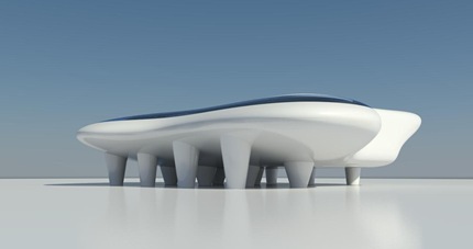
I quickly did this pancake shape in AutoCAD 2010 using the new mesh tools and then converted to solid and saved the DWG.

image

I then imported this DWG into a mass family and then loaded this into a project. I was then able to skin the mass with walls and curtain wall as well as get the area of the floors plates.

 2010 mass

Ok, it won't win any awards but as a quick design exercise, this is just amazing.On a side note this form was brought into Revit Architecture 2009 and it only took me 30 minutes from inception in AutoCAD until completed renders in Revit.

2010 image

Structural Column shown in every plan view - solution

Okay, I ran into this issue...

When a Structural Column is located in a plan view, but the top of the column is way down this level, so it should not appear there, but it is!

However, when you look to the Element Properties of that Structural Column you will see that within the Analytical Model group the parameter "Top Vertical Projection" is set to "Top of Column". I do not know why it is set this way, but it appears to be this way sometimes...

Change this parameter to "Auto-detect". Click on OK and now your plan view looks right again.

More Topmod and Revit

A couple of blog followers have asked whether you can convert a form created in Topmod into usable geometry within Revit, ie. a solid. At present this is not possible in Topmod, although there are a number of tools on the internet that will you to convert an obj file (Topmods file format) into a Acsi solid. Whether this will provide you with usable results, I couldn't say.

Nevertheless, what I did recently though, was create a form in Topmod open that within 3dsmax and then convert the mesh into a editable polymesh.

image 

Once you've got a polymesh, you can then export this from 3dsmax as a DWG and then utilize this within a Revit family,  but you still aren't able to slice the geometry to get volume or floor areas like you can with an Acsi solid.

image

However, you are able to skin up the geometry with curtain wall systems and walls. This allows you to get some interesting geometric forms out of Revit! Below are a few renders from the Revit utilizing the geometry from Topmod.

image

image

This is certainly an interesting design workflow and allows you to produce some compelling results very quickly. Now, if only we had a tool which could convert a polymesh into a solid! then we'd be laughing.......

Edit System Panel in Revit

Did you know that you can edit a System panel in a Curtain System within Revit ! I just figured it out. How?


First create a Curtain System using eg Massing in Revit and putting a Curtain System on it(see images).


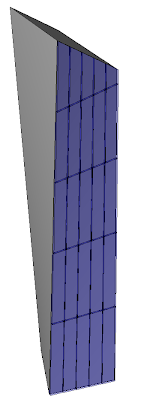
This Curtain System uses a System Panel type Glazed
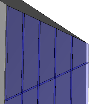
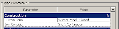
Select the System Panel that you want to Edit and UNPIN the Panel
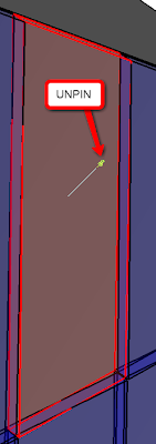
Now, you can select the Edit button in the Option bar

Now, the Family Editor is started and you can change the System Panel.

That's all. In fact, the original System Panel is replaced by an Inplace Family

Revit Hauer cw download

image

A number of readers have asked if I could upload and share the Hauer panel from the last post. I've zipped up the file, click here for download. This is a stripped down version of the project which includes the curtain wall system as well as the families. Enjoy. :-)